A shaker doesn't distinguish between the fixture and the device under test (DUT). It sees one combined dynamic system. If the fixture flexes, resonates, or twists where it shouldn't, the data coming off the accelerometer reflects the fixture's behavior, not the product's. A perfectly good part can "fail" a test because of hardware that was never the focus of anyone's attention.
This article covers the core design principles that keep fixtures out of trouble — natural frequency, material stiffness, symmetry, and fastening — along with the most common mistakes engineers make and how to verify a fixture's behavior before it ever sees a full-level test.
Key Takeaways
- Design fixture natural frequency 2-3x higher than peak test frequency to avoid instability
- Aluminum typically beats steel on stiffness-to-weight once geometry is factored in
- Resonance, weak fastening, geometry mismatch, and overloading cause most preventable fixture failures
- Poor fixture design causes over-testing or under-testing, raising cost and liability risk
- An ISO/IEC 17025-accredited lab with in-house fixture expertise reduces risk on complex programs
What Is a Vibration Test Fixture & Why Proper Design Matters
A vibration test fixture is the mechanical interface that mounts the DUT to the shaker table. It has three jobs:
- Hold the part in the correct orientation
- Distribute the applied load evenly
- Transmit vibration energy along the intended axis without adding or subtracting from it
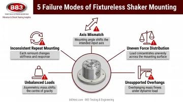
Bolting a part directly to the shaker head sounds simpler, but it rarely works in practice. Common problems include:
- Axis mismatch — the product's critical mounting orientation doesn't line up with the shaker's drive axis
- Uneven force distribution — asymmetric parts load the table unevenly, inducing wobble
- Unsupported overhangs — sections of the DUT hang past the table edge with no bracing
- Unbalanced loads — mass concentrated off-center strains the armature
- Inconsistent repeat mounting — no fixture means no repeatable reference between test runs
Because the fixture and DUT move as a single system, MIL-STD-810H Method 514.8 addresses this directly. Paragraph 4.2.2.4.a states that a test fixture survey should be conducted before testing begins, specifically so the fixture's own structural characteristics don't introduce uncontrolled resonances into the test.
That's advisory language, not an absolute mandate, but it reflects an industry consensus: skip the survey and you're gambling on data quality.
Core Design Principles for Vibration Test Fixtures
Good fixture design comes down to a handful of interlocking decisions. Get these right and most downstream problems disappear on their own.
Natural Frequency and the 2-3x Rule
When a fixture's own resonance falls inside the test's control bandwidth, the controller tries to drive straight through it. That produces control instability, excessive drive levels, and in worse cases, damage to the shaker or the fixture itself.
The common industry guideline, per Vibration Research, is to design the fixture's first mode at 2-3x the highest test frequency. A test running to 2,000 Hz should have a fixture with a first resonance at 4,000-6,000 Hz or higher.
Notching or bandwidth-limiting can manage an isolated in-band resonance after the fact. But treat these as workarounds, not design strategy. If you're notching heavily, the fixture needed a redesign before it ever reached the shaker.
Stiffness-to-Mass Ratio and Material Selection
Every fixture design balances two competing needs: enough rigidity to keep resonance out of the test band, and low enough mass that the shaker isn't burning force capacity moving the fixture instead of the product.
On paper, aluminum, steel, and magnesium have nearly identical specific stiffness (Young's Modulus divided by density), all clustering around 25.4-25.5 MJ/kg. That means material choice alone doesn't explain aluminum's dominance in fixture shops. Section geometry does.
| Material | Typical Fixture Role | Key Tradeoff |
|---|---|---|
| Aluminum 6061-T6 | Industry-standard choice | Best stiffness-per-pound once thickness is optimized |
| Steel (1018) | Occasional heavy-duty use | Added mass often lowers natural frequency |
| Magnesium AZ31B | Premium, high-performance builds | Excellent stiffness-to-weight, difficult to machine |
Engineering comparisons show why: a ¾-inch aluminum plate at the same mass as a ¼-inch steel plate delivers roughly 9x the bending stiffness, because tripling the thickness increases the moment of inertia by a factor of 27, far outweighing steel's higher raw modulus.

That's why aluminum remains the default material for most fixture programs, and why simply swapping to steel "for strength" often backfires by lowering the fixture's natural frequency instead of raising it.
Magnesium earns its place in high-performance applications where every gram matters, but it's harder to machine and costs more. Most programs don't need it.
Symmetry, Geometry & Simplicity
Symmetrical fixtures transmit vibration evenly across the mounting surface and keep cross-axis motion to a minimum. Asymmetric or overly complex designs invite unintended rotation and torsional modes — the kind of "mysterious resonance" that shows up on an accelerometer with no obvious explanation.
Watch for these geometry red flags:
- Long overhangs that extend past the fixture's supported base
- Tall, unsupported vertical structures
- Thin sections or unnecessary added components
Each of these introduces bending modes that get excited easily during random vibration testing. Once excited, they generate sensor readings that have nothing to do with how the actual product behaves in the field.
Fastener Selection & Boundary Conditions
Fasteners take a beating under sustained vibration, and a loose bolt can invalidate a test long before anyone notices.
Best practices worth following on every build:
- Prefer through-bolts over tapped holes: if a tapped hole into aluminum is unavoidable, use a steel thread insert
- Torque to spec and keep exposed bolt length short, with full thread engagement
- Use vibration-resistant fasteners or thread lockers rather than relying on friction alone
- Schedule periodic torque checks: loosening from vibration is often gradual and easy to miss
Boundary conditions matter just as much as the fasteners themselves. Mounting method, torque values, gaskets, and isolators all determine the stress the DUT actually experiences.
Over-constrain the part and you artificially stiffen it; under-constrain it and you permit motion that wouldn't happen in real-world service. Every mounting detail should replicate the field installation and be documented so the next test run can repeat it exactly.
Common Problems in Vibration Test Fixture Design (and How to Fix Them)
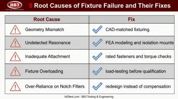
Most fixture failures trace back to one of five root causes. Here's what to watch for and how each gets resolved.
- Geometry mismatch: A fixture that doesn't align with the product's mounting points can misalign or damage the DUT during setup. Fix this through close collaboration between test engineers and the product design team, using CAD-matched fixturing instead of a generic plate.
- Undetected resonance: An unvalidated fixture can amplify certain frequencies and skew results without anyone realizing it. FEA modeling before fabrication, paired with damping through isolation mounts, addresses this — heavy notching after the fact does not.
- Inadequate attachment: Weak clamping or under-torqued bolts risk DUT detachment mid-test. Correctly rated fasteners, precise torque values, and periodic inspections during longer test campaigns solve this.
- Fixture overloading: A DUT heavier or larger than the fixture's rated capacity can cause structural failure. Load-testing the fixture before qualifying it for client use catches this before it becomes a mid-test surprise.
- Over-reliance on notch filters: Notching can manage one isolated resonance. Repeated or heavy notching across a test usually means the fixture needs a redesign, not more compensation.
Over-testing versus under-testing ties these causes together as the ultimate consequence of poor fixture design. MIL-STD-810H frames it as the central risk test engineers face:
| Fixture Behavior | Consequence |
|---|---|
| Amplifies frequencies (over-testing) | Unnecessary cost, false failures |
| Damps or misdirects energy (under-testing) | Field failures, product recalls |
A validated fixture is the safeguard against both extremes.
Verifying Fixture Performance Before and During Testing
Design principles only matter if you confirm they worked. That happens in two stages: before the fixture ever sees a full-level test, and continuously while the test is running.
Pre-Test Validation
Start with FEA or normal mode simulation to predict the fixture's natural frequencies and mode shapes before fabrication. This step catches problematic bending modes on a computer screen instead of on the shaker.
Once the fixture is built, run a physical resonance or modal survey (a low-level random sweep with accelerometers instrumented on the fixture) to confirm the as-built hardware matches the FEA prediction.
This step often reveals issues the simulation couldn't: loose joints, fastener compliance, or manufacturing tolerances that shift the real-world resonance away from the model.
In-Test Monitoring
Two signals during a live test usually mean the fixture, not the product, needs attention:
- Rising drive levels: the shaker is working harder than expected, often a sign of fixture resonance or an anti-resonance condition demanding more force than calculated
- Low coherence between the drive and response signals: this points to fixture dynamics, a slipping interface, or nonlinear behavior rather than a genuine DUT response
Fixture requirements also shift with the type of test. A fixture that performs fine for broadband, repetitive-shock testing may be entirely wrong for an electrodynamic shaker.
Repetitive-shock test methods use repetitive shock and tolerate compliant, simple fixtures for broadband discovery testing. Electrodynamic testing demands the opposite: a stiff, well-characterized fixture built for precision control. Don't assume a fixture is transferable between the two; at B83, our engineers design and validate fixtures specifically for each shaker's dynamics rather than reusing hardware across test types.
Partnering with an Independent Test Lab for Fixture Design
Designing a fixture that survives FEA review, passes a modal survey, and holds up through a full qualification program takes specialized skill. Shaker-specific tuning, structural modeling, and cross-industry experience are skills many product teams simply don't maintain in-house. For complex or first-time qualification programs, this is often the point where outsourcing makes sense.
One question worth clarifying before any test plan is signed: who owns the fixture once it's built? Many independent labs retain ownership and responsibility for a fixture's dynamic performance, since they can't guarantee how it behaves once it's moved to a different shaker system. Getting this settled upfront avoids confusion later.
B83 Testing & Engineering addresses this ownership question directly, as an engineer-owned, ISO/IEC 17025:2017 ANAB-accredited independent lab based in Milwaukee, Wisconsin, operating since 2002. The team designs custom vibration fixtures matched to its fleet of five electrodynamic shakers, with force capacity ranging from 4,000 to 18,000 lbf, for clients across automotive, aerospace, medical device, and construction equipment industries.
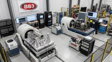
That range of shaker capacity on-site means fixtures get right-sized to the application, rather than forced through a one-size-fits-all setup:
- Lighter, more precise builds for sensitive electronics near the low end
- Structurally robust designs for large mechanical assemblies at the high end
Frequently Asked Questions
What is a vibration test fixture and why is it needed?
A vibration test fixture mounts the device under test (DUT) to the shaker table, distributes load, and transmits vibration in the correct orientation. Direct mounting often fails due to axis mismatch and uneven force distribution across the part.
What is the ideal natural frequency for a vibration test fixture?
The common guideline is 2-3x the highest test frequency. A test running to 2,000 Hz calls for a fixture with a first resonance at 4,000-6,000 Hz or above.
Is aluminum or steel better for vibration test fixtures?
Aluminum is the industry standard, thanks to its stiffness-to-weight advantage once section thickness is optimized. Steel's added mass typically lowers natural frequency, and magnesium remains a premium option for high-performance builds.
How can I tell if my fixture has a resonance problem during a test?
Watch for rising drive levels and low coherence between the drive and response signals. Both point to fixture resonance or a slipping interface rather than an actual product response.
Can the same fixture be used across different vibration test setups?
Usually not. Broadband, repetitive-shock methods tolerate compliant, simple fixtures for discovery testing, while electrodynamic testing requires rigid, precise fixtures...
Who owns the test fixture after a lab builds it for my test program?
Many labs retain ownership and liability for a fixture's dynamic performance, since behavior can't be guaranteed on a different shaker system. Clarify this in the test plan before work begins.