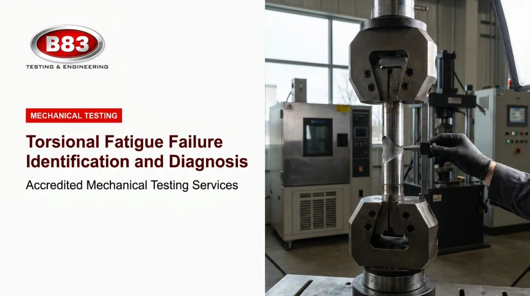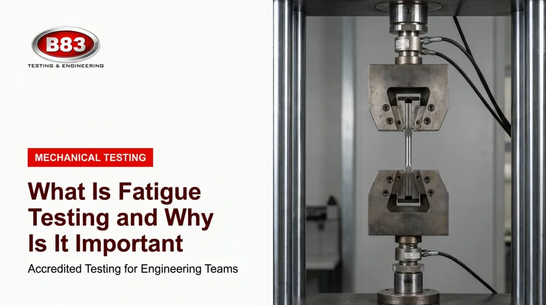

Introduction
A shaft rated for 50,000 psi never sees a load anywhere close to that limit. It still snaps in half after two years of service. That's the paradox of mechanical fatigue: parts fail even when no single load ever exceeds what the material can handle.
This isn't a rare edge case. Fatigue contributes to an estimated 90% of all mechanical service failures, according to ASM International's Elements of Metallurgy and Engineering Alloys.
The real problem is that fatigue cracks grow invisibly. A part can pass initial inspection, survive a single stress test, and still fracture in the field months later. That gap drives warranty claims, recalls, and safety incidents.
This guide breaks down what mechanical fatigue actually is, why it happens, the warning signs to watch for, and how design and testing practices catch it before it reaches a customer.
Key Takeaways
- Fatigue is progressive cracking caused by repeated cyclic loading, not one overload event
- Cracks can start and grow well below a material's rated yield strength
- Failure develops in three stages: initiation, propagation, and final fracture
- Geometry, material selection, and cyclic testing reduce fatigue risk
- Skipping validation testing turns a design flaw into a field failure
Common Causes of Mechanical Fatigue
Mechanical fatigue is damage that accumulates inside a material's internal structure from repeated or fluctuating stress. Static overload, by contrast, happens when one load event simply exceeds what the part can carry. Fatigue is slower and far sneakier.
Here's the part that catches engineers off guard: fatigue cracks can initiate and grow at stress levels well below the material's yield strength. A component can look structurally sound on paper and still be quietly accumulating damage with every cycle.
The Three Stages of Fatigue Failure
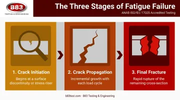
Fatigue failure isn't instant. It moves through three distinct phases:
- Crack initiation: A microscopic crack starts at a stress riser or surface discontinuity, where localized plastic deformation and work hardening create the first weak point.
- Crack propagation: The crack grows a tiny amount with each load cycle, often with zero visible external sign. How much of the total life this stage consumes depends on stress level, defect size, and load type, with no fixed rule.
- Final fracture: Once the remaining cross-section can't carry the load, the part breaks rapidly, often leaving a fracture surface that looks brittle even in a ductile material.
Fatigue also shows up differently depending on the loading environment. High-cycle fatigue (generally north of 100,000 cycles), low-cycle fatigue, thermal fatigue, and corrosion fatigue each demand different design and testing approaches.
Cause 1: Cyclic or Repeated Loading
Vibration, rotation, pressure cycling, and repeated startup/shutdown events all generate the fluctuating stress that fatigue needs to take hold. Common scenarios include:
- Rotating shafts and bearings under continuous load reversal
- Vibrating machinery on production lines or vehicles
- Pressure vessels cycling between fill and discharge
- Equipment enduring repeated field duty cycles day after day
Cause 2: Stress Concentrations
Sharp corners, holes, notches, keyways, and weld toes amplify local stress well above nominal levels. These geometric features become ideal crack nucleation sites. Watch for:
- Abrupt section changes in machined parts
- Poorly profiled weld toes
- Thread roots and fastener holes in load-bearing structures
Cause 3: Material and Surface Defects
Surface scratches, corrosion pits, machining marks, inclusions, and porosity all reduce local fatigue resistance. Because initiation is largely a surface phenomenon, a flaw at the surface does more damage than the same flaw buried inside the part. Common culprits include:
- Rough machining finishes that leave stress-raising tool marks
- Field corrosion pitting during service life
- Internal casting or weld defects introduced during manufacturing
Cause 4: Environmental Factors and Unrealistic Load Assumptions
Temperature cycling and corrosive environments shorten fatigue life beyond what a clean lab test might predict. So does underestimating real operating cycles during design. Common examples:
- Thermal cycling in exhaust systems or heat exchangers
- Offshore and marine equipment exposed to salt spray and constant motion
- Products where lab test conditions never matched actual field usage
What Happens If Mechanical Fatigue Is Ignored
Ignoring fatigue risk doesn't produce a slow decline. It produces a sudden, often catastrophic failure with little to no warning.
The 1954 de Havilland Comet G-ALYP breakup is a documented example. After 1,290 pressurized flights, the aircraft's cabin fractured near Elba, killing everyone aboard.
Investigators traced the failure to fatigue cracking that started at a bolt hole near a window corner, a classic stress concentration under repeated cyclic pressurization. This finding comes from research published in Engineering Failure Analysis. A small, invisible crack grew flight after flight until the structure could no longer hold.
Ignoring fatigue in less dramatic settings still carries real cost:
- Safety incidents when a critical component fails without warning
- Expensive recalls and warranty claims once a design flaw shows up across a fleet of units
- Long-term reputational damage that outlasts the cost of the recall itself
Warning Signs You're About to Experience Fatigue Failure
Because fatigue damage builds internally before it's visible, indirect indicators are usually the best early warning:
- Unexpected changes in vibration, noise, or performance during normal operation
- Recurring cracks or repairs concentrated at the same detail or location, a sign that stress concentration is doing damage repeatedly
- NDT indications or visible surface cracking at known stress risers such as welds, bolt holes, or thread roots
Any one of these should trigger a closer look, not a wait-and-see approach.
How to Prevent Mechanical Fatigue Failure
There's no single fix for fatigue. Prevention comes from combining smarter design, material and surface control, and validation testing that mirrors real-world use.
Improve Geometry and Reduce Stress Concentrations
Specify larger fillet radii, smoother transitions, and eliminate unnecessary sharp corners or abrupt section changes. A generous fillet at a shaft shoulder, for example, can lower the stress concentration factor from over 3.0 to under 1.5, directly extending fatigue life in that area. Reducing local stress amplification removes the starting point cracks need. Implement this during initial design and CAD/FEA review, before tooling gets finalized. Fixing geometry after tooling exists is far more expensive.
Select Fatigue-Resistant Materials and Surface Treatments
Choose alloys with proven fatigue performance for the application, and apply treatments like shot peening or polishing to critical surfaces.
NASA testing on carburized and hardened AISI 9310 gears found that shot-peened parts achieved 1.6 times the pitting-fatigue life of unpeened gears, largely due to beneficial compressive residual stress at the surface, according to NASA's testing on shot-peened gear surfaces. Results vary by material and process, but the underlying mechanism, removing surface flaws and adding compressive stress, holds up broadly.
Validate Real-World Performance With Cyclic Fatigue and Vibration Testing
Design changes and material upgrades are theories until they're tested under representative loading. This is where an accredited independent lab like B83 Testing & Engineering comes in. B83 runs cyclic fatigue, vibration, and mechanical shock testing, plus field data replication, that mimics actual duty cycles before a product ships.
- Servo-hydraulic systems handle axial and torsional fatigue on structural components and full assemblies
- A fleet of five electro-dynamic shakers, ranging from 4,000 to 18,000 lbf, covers everything from delicate electronic subsystems to heavy off-road components
- Environmental chambers simulate temperatures from -100°F to +500°F, useful for thermal cycling fatigue in exhaust or heat-exchanger parts
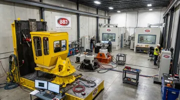
Running this at the prototype and pre-production stage, and again after any major design or material change, surfaces weak points in the lab instead of in a customer's hands.
Establish Ongoing Inspection and Monitoring Programs
Once a product is in service, schedule regular non-destructive testing, crack monitoring, and residual life reassessment for safety-critical or high-cycle components. Catching a propagating crack while it's still small enough to repair beats discovering it after final fracture. Tie these inspections to actual usage:
- Track cycles and operating hours, not calendar time alone
- Use liquid penetrant or magnetic particle inspection for surface cracks at known stress risers
- Reserve ultrasonic or eddy current methods for subsurface indications
A few operational habits make this stick over a product's full lifecycle:
- Train design, manufacturing, and maintenance teams to recognize fatigue-critical details and report early warning signs
- Document load history, repairs, and test results so cumulative damage can be tracked across a product's service life
- Use strain gauges or vibration sensors on critical equipment to flag abnormal load patterns before they cause visible damage
Conclusion
Mechanical fatigue isn't random. It has identifiable causes rooted in cyclic loading, stress concentration, and material or surface defects, and every one of those causes can be designed around, tested for, or monitored.
Solid design practices catch fatigue risk on paper. Independent, ISO/IEC 17025-accredited testing, such as the fatigue validation B83 Testing & Engineering provides, catches what design alone can't predict. Together, they turn fatigue prevention from a theoretical exercise into a documented, defensible part of product development, one that holds up in the field and in front of a liability claim.
Frequently Asked Questions
What causes mechanical fatigue?
Fatigue results from repeated cyclic stress acting at points of weakness such as stress concentrations, material defects, or unexpected environmental conditions. It can occur even when every individual load stays below the material's yield strength.
What are the different types of fatigue?
The main categories are high-cycle, low-cycle, thermal, corrosion, and fretting fatigue. They differ by load amplitude, cycle count, and the environment the component operates in.
What are the three stages of fatigue failure?
Fatigue progresses through crack initiation, crack propagation, and final fracture. Initiation starts at a stress riser, propagation grows the crack cycle by cycle, and fracture occurs once the remaining material can't hold the load.
Can fatigue failure happen below a material's yield strength?
Yes. Local cyclic plasticity at stress raisers can develop damage even when nominal stress stays below yield, which is exactly what makes fatigue more dangerous than static overload.
How is fatigue failure different from a one-time overload failure?
A static overload happens when a single load exceeds the material's capacity all at once. Fatigue is different: repeated cycles of acceptable-looking loads gradually damage the material until it can no longer hold.
How does testing help prevent mechanical fatigue failure?
Cyclic fatigue and vibration testing under accredited, controlled conditions reveals a product's real-world fatigue life before launch. B83's testing services help validate designs and catch weak points before products reach the market.