Shafts, drivelines, couplings, and gearboxes across automotive, rail, agricultural, construction, and industrial equipment all carry this risk. Get the diagnosis wrong, and you're looking at repeat warranty claims, safety exposure, and a dented reputation with the customer who trusted your design.
The financial backdrop makes this worse. Siemens and Senseye's 2022 industrial study estimated that unplanned downtime costs Fortune Global 500 manufacturers roughly $1.5 trillion annually, or 11% of total turnover. That's the scale of exposure a single misdiagnosed shaft failure can feed into.
This article walks through how to visually identify torsional fatigue, confirm the root cause with real measurement and modeling, and avoid the mistakes that send investigations in the wrong direction.
Key Takeaways
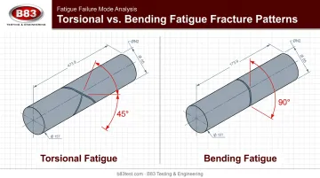
- 45-degree fracture angles distinguish torsional fatigue from bending fatigue's 90-degree breaks
- Fracture zone size, keyway origins, and gear wear patterns offer quick visual clues—not root-cause confirmation
- Root causes fall into three categories: machine characteristics, reversing loads, and torsional resonance
- Confirming the diagnosis requires torque and vibration measurement plus Holzer or matrix modeling
- Independent lab validation ensures your fix actually solves the problem instead of masking it
What Is Torsional Fatigue Failure?
Torsional fatigue failure is crack initiation and growth caused by cyclic shear stress acting around a shaft's longitudinal axis. Unlike a single overload snap, it builds gradually through repeated twisting, until the remaining cross-section can't hold and the part fractures suddenly.
It shows up most often in:
- Drive shafts and pump shafts
- Splined shafts and shaft-hub interfaces
- Couplings and gearbox input/output shafts
- Any rotating component exposed to variable torque
Once a failure turns up in one of these components, the fracture surface itself tells you what kind of loading caused it.
Fracture Angle: The First Clue
The fastest way to separate torsional fatigue from bending fatigue is the fracture angle relative to the shaft's centerline. A break closer to 45 degrees points to torsion. A break closer to 90 degrees, running perpendicular to the shaft axis, points to bending.
Angles in between often mean both loading types were present. Don't rule out either mechanism just because one appears dominant.
Why Identifying and Diagnosing Torsional Fatigue Matters
Misreading torsional fatigue as a different failure mode, such as overload or material defect, is how repeat failures happen. The team fixes the symptom, ships the redesign, and the same shaft breaks again in the field.
Correct identification delivers real operational payoff:
- Prevents costly repeat failures and unplanned downtime
- Reduces safety risk from sudden shaft or coupling fracture
- Supports accurate root cause analysis instead of surface-level fixes
- Protects against warranty claims and liability exposure
- Enables engineering teams to make data-backed design or material changes
Skipping this step doesn't just cost money. It erodes trust with the customer who now has a second failure on the same component.
How to Identify Torsional Fatigue Failure: Visual & Fracture Analysis
Reading the Fracture Face
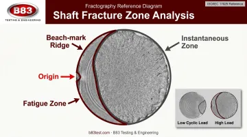
Every fatigue fracture has three zones: the origin point, the fatigue zone with visible progression lines (often called beach marks), and the instantaneous zone where the part finally gave way.
The relative size of these zones tells you about loading severity: a large fatigue zone with a small instantaneous zone points to lower cyclic load sustained over a long time, while a small fatigue zone with a large instantaneous zone signals higher load and a faster path to failure.
Keyway Origins and the "Peeled" Look
When a shaft fits inside a hub or coupling, torsional fatigue cracks typically start at the base of the keyway, then spiral around the shaft's circumference as they grow. The result often looks like the surface was peeled rather than snapped clean.
Reversing torsional fatigue adds a twist, literally. When load direction alternates, you can see two separate 45-degree cracks instead of one.
On splined shafts, this sometimes produces a starburst pattern radiating from multiple spline roots. It's a less common signature, but engineers who don't know to look for it will misread the fracture as a single-direction torsional event.
Secondary Evidence: Wear and Vibration
Uneven or double-sided wear on gear teeth or coupling faces in an otherwise unidirectional machine is a red flag. It suggests torsional vibration is at work, not just steady running torque.
Common mistake: Assuming any fracture near 45 degrees is pure torsion without checking for bending contribution. A mixed-mode fracture can mislead the entire root cause investigation if the angle is treated as conclusive on its own.
Vibration phase and spectra readings help rule out misalignment as the cause of that uneven wear, pointing the investigation back toward torsional loading.
Diagnosing the Root Cause: Torsional Measurement & Analysis
Visual evidence tells you what happened. Measurement and modeling tell you why. Torque variation that drives torsional fatigue generally comes from three sources:
- Machine characteristics: gear mesh frequency, vane pass frequency, motor faults, fluid pulsation
- Reversing loads: direction changes in operating torque
- Torsional resonance: a forcing frequency coinciding with a system natural frequency
Choosing a Measurement Method
Two approaches dominate this kind of testing:
| Method | What it captures | Best for |
|---|---|---|
| Strain gauge + wireless transmitter | Torque and vibration | Direct torque measurement at a specific section |
| Accelerometer ring | Vibration only | Easier install, higher-frequency content |
Strain gauges give you absolute torque through DC-coupled measurement, plus torsional vibration through AC-coupled measurement converted into a frequency spectrum. Accelerometer rings skip direct torque but pick up angular acceleration, useful when the concern is high-frequency vibration rather than steady load.
Choosing between the two often comes down to what the investigation actually needs: strain gauges for absolute torque values, accelerometers for pure high-frequency vibration content.
Modeling the System
Once resonance is suspected, a Holzer or eigenvector/matrix model calculates the system's torsional natural frequencies and mode shapes from inertia and stiffness data. This step is where most investigations fall short. Skipping model validation, or relying on visual inspection alone, is the single most common mistake in torsional fatigue diagnosis. A model result only counts once labs like B83 Testing & Engineering check it against real measured vibration data from the actual machine.
Case Study: Diagnosing a Recurring Torsional Fatigue Failure
Consider an illustrative scenario common across gearbox applications: a gearbox input shaft and gear keep experiencing torsional fatigue failures, and the problem gets worse after a coupling replacement.
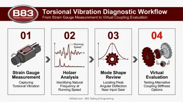
The diagnostic path typically looks like this:
- Strain gauge measurement captures torsional vibration on the running system
- Holzer analysis reveals a torsional natural frequency landing right at motor running speed
- Mode shape review identifies peak angular deflection occurring near the input gear, exactly where failures keep starting
- Virtual evaluation of several alternative coupling stiffness options, modeled before any physical part is built or swapped
Independent testing labs such as B83 Testing & Engineering routinely combine strain gauge measurement, modal analysis, and virtual modeling like this to isolate root causes before any hardware changes are made.
This approach avoids the expensive trial-and-error cycle of installing one coupling after another and waiting to see which one fails next. In cases like this, the goal is a coupling stiffness change that shifts the natural frequency away from running speed and meaningfully reduces angular deflection at the input gear.
Every system responds differently, so treat the diagnostic steps and outcomes above as illustrative rather than a guaranteed path for your own application.
How B83 Testing & Engineering Can Help
Confirming a torsional fatigue root cause takes more than a fracture inspection. It takes precise measurement, validated modeling, and independent testing before a design change goes into production.
B83 Testing & Engineering delivers that combination as an engineer-owned, ISO/IEC 17025:2017 ANAB-accredited independent testing laboratory in Milwaukee, Wisconsin, performing cyclic fatigue, load/displacement, and vibration testing to help confirm torsional root causes and validate fixes.
Relevant capabilities include:
- Custom fixture design for shafts, couplings, and drivetrain components, tailored to each part's geometry
- Five electro-dynamic shakers, ranging from 4,000 to 18,000 lbf, for simulating real operating loads
- RPC field data replication, reproducing actual torsional and vibration conditions recorded from a client's field application in a controlled lab setting
For clients across automotive, rail, agricultural, construction, and industrial equipment programs, this translates to:
- Faster, evidence-based root cause confirmation
- Reduced risk of repeat failures and warranty costs
- Independent third-party validation that strengthens design decisions before parts ship
If your team is chasing a recurring shaft or coupling failure, B83's engineers can talk through fixture design and test approach for your specific component.
Frequently Asked Questions
Torsional fatigue diagnosis combines visual fracture analysis with torque and vibration measurement backed by modeling. Ongoing monitoring after a fix helps catch resonance issues before they turn into another failure.
What is cyclic fatigue and torsional stress?
Cyclic fatigue is progressive material damage from repeated loading over time. Torsional stress is the shear stress generated when a component twists around its axis. Combined, cyclic torsional stress is a common driver of shaft fatigue failure.
Is torsional stress a normal stress?
No. Torsional stress is a shear stress, not a normal stress, though torsion can induce a smaller secondary axial (normal) stress in constrained components, as shown in ASM International's failure analysis of an axle shaft.
What does high torsional stiffness mean?
High torsional stiffness means a component resists twisting deformation under applied torque. This directly affects a system's natural frequency and can shift resonance points away from, or into, dangerous operating ranges.
What causes torsional fatigue failure in shafts?
Three main causes: repetitive machine-driven torque variation, reversing loads, and torsional resonance. Poor keyseat fit or finish frequently makes any of these three worse.
How can torsional vibration be measured?
Strain gauge systems with wireless telemetry capture absolute torque and torsional vibration together. Accelerometer-ring systems capture vibration only but install more easily and cover higher frequencies.
Can torsional fatigue failures be prevented?
Yes, in most cases. Correct machining and assembly, identifying the specific torque variation source, and correcting torsional resonance through modeling and design changes prevent the majority of these failures.