
This is exactly the failure mode a temperature cycling test (TCT) is built to catch before a product ever ships. Static, room-temperature inspection tells you almost nothing about how a part behaves after hundreds of thermal expansion and contraction cycles.
TCT results feed directly into quality control decisions, warranty budgets, safety certifications, and product uptime across automotive, aerospace, medical device, and electronics manufacturing. A single overlooked thermal fatigue mechanism can mean a recall, a warranty spike, or a field failure with real safety consequences.
This guide defines temperature cycling testing, walks through how it works step by step, compares it against thermal shock testing, and explains how working with an independent accredited lab helps manufacturers catch these problems before a product ever leaves the building.
Key Takeaways
- TCT repeatedly alternates high and low temperature extremes to expose thermal expansion/contraction fatigue failures
- TCT differs from thermal shock testing in transition speed and the failure modes it uncovers
- Standards like JEDEC JESD22-A104, MIL-STD-883, and ISO 16750-4 define test parameters by industry
- Common failures include solder joint cracking, die/package cracking, and seal degradation
- An ISO/IEC 17025-accredited lab ensures results hold up for qualification and regulatory use
What Is a Temperature Cycling Test?
A temperature cycling test is a reliability test that subjects a product or component to a set number of cycles between a high and low temperature extreme. The goal is to accelerate the fatigue failures that show up when bonded materials with different coefficients of thermal expansion (CTE) repeatedly expand and contract against each other.
Picture a solder joint bonding a ceramic chip to a fiberglass circuit board. The two materials expand at different rates as temperature rises and contract differently as it falls. Do that thousands of times, and the joint eventually cracks, even though it looked perfectly fine on day one.
Reproducing that failure pattern reliably depends on controlling exactly how the temperature changes, not just the range it covers. TCT is typically run in a single chamber, with the same chamber ramping air temperature up and down rather than shuttling the part between two separate zones. Transition rates stay moderate: JEDEC's JESD22-A104F.01 standard caps its air/gas temperature cycling ramp rate at 15°C per minute, measured across the 10%–90% portion of the range. That's the key distinction from thermal shock testing, which moves much faster.
Manufacturers use TCT at multiple points in a product's life:
- Design validation — confirming a new design survives its expected thermal environment
- Quality assurance — screening production lots for material or process defects
- Reliability qualification — generating data for certification and customer sign-off
Common Standards Governing Temperature Cycling Tests
No single universal temperature range or cycle count applies to every product. Each governing standard defines its own parameters based on the industry and application.
| Standard | Primary Use | Key Parameters |
|---|---|---|
| JEDEC JESD22-A104F.01 | Semiconductors, components | Conditions range from -55°C/+85°C to -65°C/+150°C; ramp capped at 15°C/min |
| MIL-STD-883 Method 1010.9 | Military microcircuits | Conditions A–F span -65°C/+85°C up to -65°C/+300°C; minimum 10 cycles default |
| MIL-STD-810 | Military/aerospace hardware | No fixed profile — requires tailoring from the product's life-cycle environment |
| IEC 60068-2-14 | General electronics | Test Nb (specified rate) vs. Test Na/Nc (rapid change) |
| ISO 16750-4 | Automotive electronics | Tmin -20°C to -40°C, Tmax 65°C to 180°C depending on code |
Selecting the wrong standard is a common mistake. A part designed for an automotive underhood environment tested against a consumer electronics profile won't generate meaningful reliability data: the temperature range, dwell time, and cycle count all need to match the product's actual end-use environment.
Failure Mechanisms Detected by Temperature Cycling
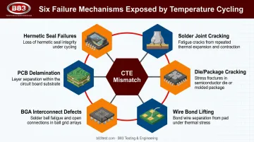
Repeated thermal cycling exposes a specific set of failure modes tied to CTE mismatch between bonded materials:
- Solder joint cracking: progressive fatigue at component-to-board connections
- Die/package cracking: internal stress from mismatched package materials
- Wire bond lifting: bond neck fractures from repeated flexing
- BGA interconnect defects: ball grid array joints weakening under cyclic strain
- PCB delamination: layer separation from Z-axis expansion mismatch
- Hermetic seal failures: loss of seal integrity in enclosed packages
These failures don't show up after one or two cycles; they accumulate gradually. That's why cycle count matters so much. A NASA/JPL study on accelerated thermal cycling found that a faster ramp profile reduced cycles-to-failure by as much as 50% compared to a slower one. The faster profile also shifted where the damage appeared, moving it from the board-side solder interface toward the package interface. Cycle counts required for meaningful data vary widely, from a minimum of 10 in some MIL-STD-883 default conditions to 500 to 1,500 cycles under AEC-Q100 automotive qualification, depending on component grade.
Why Temperature Cycling Testing Matters
Thermal fatigue that shows up in the field costs far more to fix than a defect caught in testing. TCT results connect directly to real business outcomes: fewer field failures, lower warranty claims, and a stronger position with regulators and customers.
The core benefits break down into four areas:
- Reduces liability and risk by catching design or material flaws before mass production begins
- Improves customer satisfaction and brand reputation through verified, documented durability
- Lowers long-term warranty and insurance costs through standards-based, defensible testing data
- Supports confident design decisions backed by objective failure data instead of guesswork
Consider an automotive control module that passes initial functional checks without TCT. Repeated thermal expansion and contraction can crack its solder joints, and that damage often doesn't surface until months into field service, well outside the warranty window.
A part that passes a properly scoped TCT program gives engineering teams something concrete: proof the design survives the thermal environment it was built for, not just an assumption.
How a Temperature Cycling Test Works – Step by Step
TCT follows a repeatable ramp-dwell-ramp-dwell structure. One mistake shows up often here: skipping interim functional checks or proper monitoring, which means a unit can fail internally without anyone catching it until it's too late to trace the root cause.
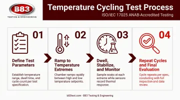
Step 1 – Define Test Parameters and Prepare the Unit
Before any cycling starts, the applicable standard, temperature range, ramp rate, dwell time, and cycle count all need to be set based on the product's actual end-use environment. Get this wrong and the test data won't hold up.
This step determines:
- Test relevance to the product's real-world conditions
- Standards compliance for certification purposes
- Repeatability across future test runs
Step 2 – Ramp to Temperature Extremes
The chamber transitions the unit under test to the specified high or low temperature within the standard's required transfer time. The specimen itself, not just the chamber's air setpoint, needs to reach the target temperature within that window.
Consistency here directly affects thermal stress accuracy across every cycle in the sequence.
Step 3 – Dwell, Stabilize, and Monitor
Once the unit reaches each temperature extreme, it's held (soaked) long enough to stabilize internally, not just at the surface. Functional or electrical testing often happens at these plateaus to catch hot-start or cold-start failures that wouldn't show up otherwise.
This step drives failure detection accuracy and determines how complete the resulting data set will be.
Step 4 – Repeat Cycles and Conduct Final Evaluation
The ramp-dwell sequence repeats for the specified cycle count. Once cycling completes, technicians perform a final visual inspection (typically at 10x to 20x magnification) along with electrical testing to identify cracks, opens, or degraded connections.
This final step determines reliability confidence and whether the data supports moving forward with a design or manufacturing change.
Temperature Cycling vs. Thermal Shock Testing
The core difference between these two tests comes down to transition speed. TCT uses gradual transitions, generally under 15°C/min, within a single chamber. Thermal shock testing moves near-instantly, often exceeding 15°C/min, by transferring the part between separate hot and cold zones.
That speed difference changes what each test reveals:
| Factor | Temperature Cycling | Thermal Shock |
|---|---|---|
| Transition speed | Gradual (under 15°C/min) | Rapid (often 15°C/min+) |
| Equipment | Single chamber, programmed ramp | Two zones or two liquid baths |
| Failure focus | Gradual fatigue, creep, stress relaxation | Localized, high-stress cracking |
| Typical use case | PCBs, automotive ECUs, long-term durability | Semiconductors, solder joints, screening |
Faster transitions create larger local temperature gradients across a part. As a result, cracking tends to shift toward package-side interfaces rather than the distributed, board-level fatigue seen under slower cycling.
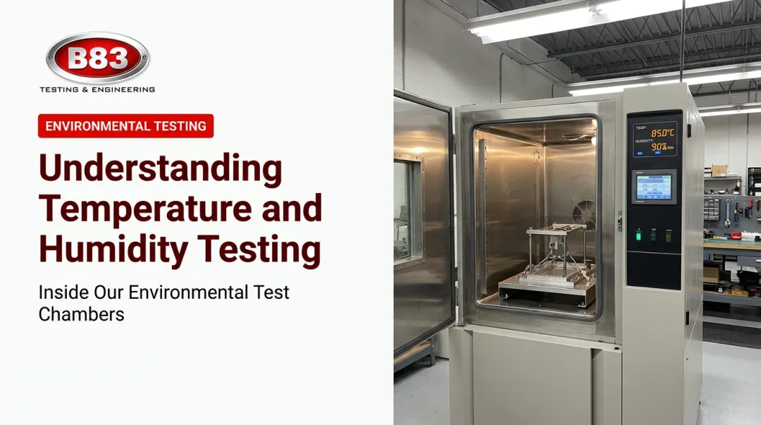
Many manufacturers run both tests together: TCT validates long-term durability, while thermal shock screens for extreme, instantaneous stress. Each approach uncovers a different piece of the reliability picture. B83 Testing & Engineering runs both in-house, using environmental chambers rated from -100°F to +500°F to cover either scenario.
How B83 Testing & Engineering Can Help
B83 Testing & Engineering is an ISO/IEC 17025:2017 accredited (ANAB), engineer-owned independent testing laboratory in Milwaukee, Wisconsin. Since 2002, B83 has run environmental and thermal testing, including temperature cycling and thermal shock, for clients in automotive, aerospace, medical device, electrical power control, and consumer product industries.
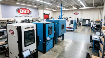
To support that range of industries, B83 operates nine environmental chambers spanning -100°F to +500°F, giving engineering teams the range needed to simulate everything from consumer electronics profiles to extreme aerospace conditions within one facility.
As an independent lab, B83 has no manufacturing stake in the outcome. That matters when the data needs to hold up for a customer audit, a regulatory submission, or an internal design review. Working with B83 offers:
- Accredited, standards-based testing trusted for qualification and regulatory purposes
- Flexible scheduling and custom fixture design built around unique product requirements
- Experienced engineering staff who can help interpret results and guide design improvements
- Long-term partnership approach, built since 2002, serving clients across the Midwest and beyond
Temperature cycling testing works best as an ongoing data source, feeding back into design refinement as products evolve. Treated that way, TCT gives manufacturers real clarity and control over how their products will actually hold up in the field.
Frequently Asked Questions
What is a temperature cycle test?
A temperature cycle test repeatedly exposes a product to alternating high and low temperature extremes to detect fatigue failures caused by mismatched material expansion rates. It reveals long-term durability issues that static inspection can't catch.
What temperature is too hot for cycling?
It depends entirely on the applicable standard and the product's tolerance. Common high-temperature setpoints range from 85°C for commercial electronics up to 200–300°C for military and aerospace-grade components under MIL-STD-883.
What are the methods of temperature testing?
The main environmental temperature test methods include temperature cycling, thermal shock, high/low temperature soak, and combined temperature-humidity testing. Each targets different failure mechanisms and product environments.
What is the difference between temperature cycling and thermal shock testing?
Temperature cycling uses gradual transitions, generally under 15°C/min, in a single chamber. Thermal shock uses near-instant transitions between separate hot and cold zones, exposing different, more localized failure modes.
How many cycles are typically required for a temperature cycling test?
Cycle counts vary by standard and purpose — as few as 10 cycles for basic MIL-STD-883 screening, up to 500 to 1,500 cycles for full AEC-Q100 automotive qualification testing.
Which industries require temperature cycling testing?
Automotive, aerospace, electronics, medical devices, and industrial equipment manufacturers all rely on TCT to meet reliability requirements and satisfy regulatory or customer qualification standards.